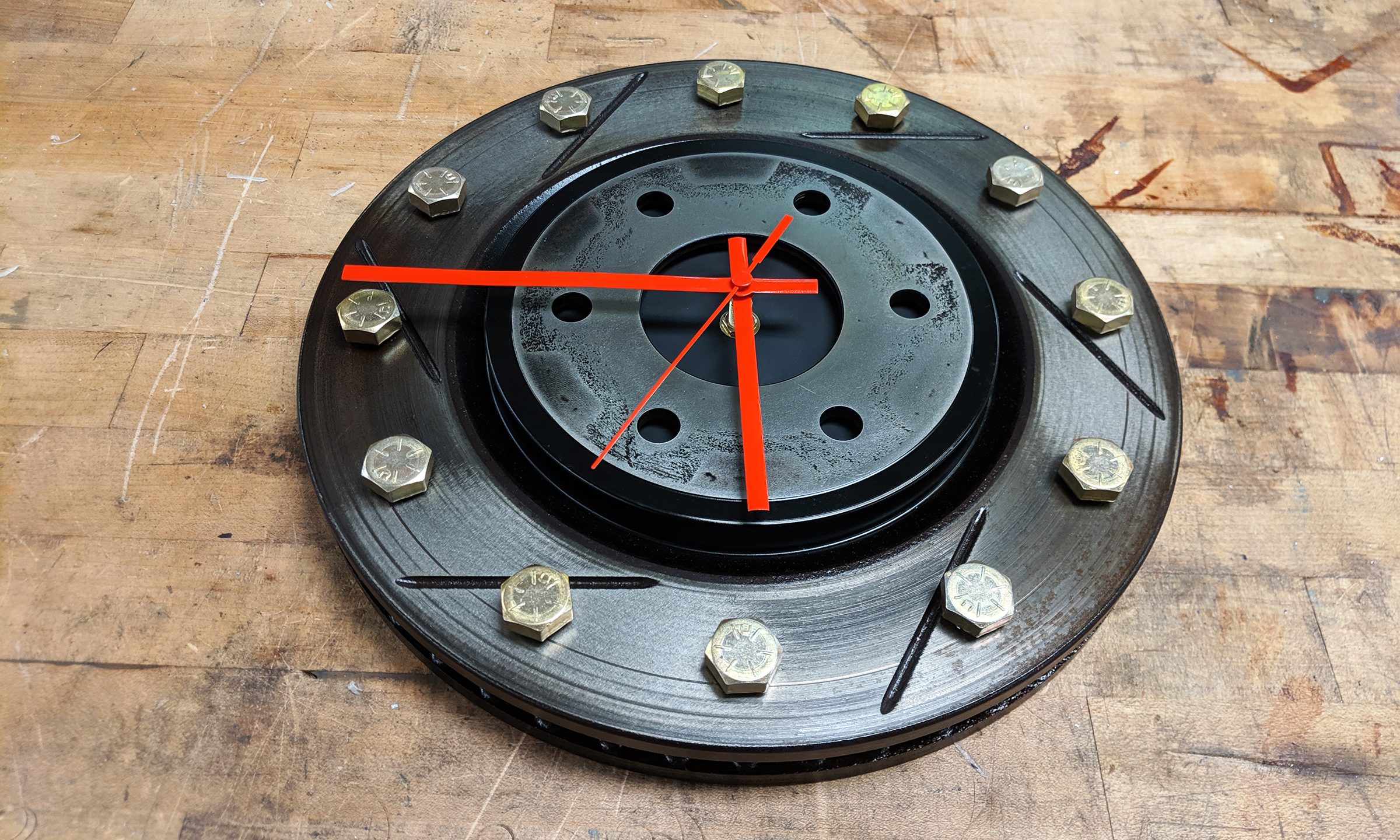
I saw several people had made brake rotor clocks and shared them on Pinterest. The idea just stuck with me and so when I recently swapped out my rotors on the Xterra I decided to keep them and make one myself. One thing that I did differently from the other ones I saw was that I decided to use big bolts in place of the numbers. I just thought some yellow zinc covered grade 8 bolts would give some good contrast and color to the project. What follows is my step by step process for how I made a 19lb clock for my garage!
Consumable Supplies List:
- Rustoleum Professional Flat Black Paint
- Rustoleum Professional Aluminum Primer
- Rustoleum Satin Clear Enamel
- Degreaser/Brake Cleaner
- VHB/Double Sided Foam Tape
- Cutting oil
Parts List:
- Used brake rotor
- Scrap piece of metal for center (about 6in in diameter and 1/16-1/8in thick)
- Clock Mechanism
- Bolts (I used 1/2-13 x 3/4in)
Tools List:
- Protractor
- Grease pencil
- Taps for your bolt size
- Drill bit for tapping your bolt size (consider oversizing just a little)
- Center drill
- Stepper drill bit
- Drill/Drill Press
- Clamps (for holding parts onto drill press)
- Vise
- Tape roll with diameter that matches inside face of rotor
- Hot glue/Hot glue gun
- Saw to cut scrap piece of metal (I used a band saw)
Steps to Make Your Own Clock
- Wash the rotor thoroughly with brake cleaner then degreaser to remove the brake pad material as well as any other dirt. The project will go smoother if you’re not dealing with a dirty rotor at each step!
- Measure and mark out where you want the bolt holes to go. I chose a diameter that was midway out on the face of the rotor braking area. You’ll need a mark every 30 degrees. Take your time on this step as it is probably the most critical single step on this project. If you don’t measure properly it will be obvious in the final assembly. I marked my locations with a grease pencil so it would be easy to remove later.
- Use a center drill to start each of the holes in the correct location. A drill bit has more of a tendency to wobble so this step reduces error that would be caused by the drill bit alone.
- Drill all the holes out. I only drilled down to the front of the back part of the rotor (more obvious in the pictures) instead of going all the way through. I figured I was going to use 3/4in long bolts so I didn’t need a threaded hole deeper than that. I chose to use ½-13 grade 8 bolts for this project. Because these bolts won’t be a structural component I chose a drill bit slightly larger than standard for this thread to make threading this hard steel easier.
- Tapping all 12 holes took a while. Take your time though and make sure to back the tap out often to clear out the chips. I found that using a normal tap and then following it with a bottoming tap worked well to thread the entire hole without risking breaking the tap.
- Once the holes were tapped I decided to take an orbital sander with 120 grit paper to the rotor to clean it up a bit. I sanded the center face for a while to clean off on the caked on gook there. I left a little bit of it though because I thought it added character and it would have taken forever to sand it all off! I also sanded 3 areas of the face of the rotor, each about ⅙ of the circumference wide, to give the finished product a little more contrast and texture.
- Next I needed to make a plate to attach my clock parts too since the hole in the center of the rotor was far too large to mount that. I wanted to find something in the shop to be a good stencil to get the diameter right and found that rolls of tape were a great option because I had lots of them of different diameters! One roll of gaffers tape I had was just the right size so I used it to draw a circle onto some scrap aluminum I had. The best part was that I could remove the marker mark on the tape by just disposing of the outer most layer when I was done.
- I cut the shape out on the bandsaw because it didn’t need to be perfect. The outside edge isn’t visible in the finished product.
- Drill a hole in the center that is slightly oversized for the threaded portion of the clock mechanism. Make sure your hole is centered!! I like drilling this kind of a hole with a stepper drill because it doesn’t bite and spin the material being drilled as easily compared to a traditional drill bit.
- I then took the orbital sander to the edges and faces of the part to get rid of burrs and rough up the surface so it would take paint better. Test fit the part to make sure it fits flat against the backside of the rotor.
- Make sure to wash the rotor and the aluminum metal disc thoroughly with lots of degreaser. The next step is their final coatings and so you want clean parts!
- Prime and paint one side of the metal disc. I have had good results using Rustoleum Professional products. I used the aluminum primer and flat black paint on this project.
- If you don’t seal the steel rotor it will rust over time. To avoid this I used Rustoleum Satin Clear Enamel as a clear sealant that would protect the metal and give it just a little shine. Be warned that some metal rust coating products are just aerosolized oil! I found this out the hard way when I used a Rustoleum Rust Inhibitor coating which turned out to basically be WD-40… I then needed to re-wash the rotor and apply a better acrylic coating. The good news is that I think the oil might have actually given the part a slightly richer color, so you can do the same process if you wish.
- With the parts fabricated it’s finally time for assembly. I first installed my ½-13 x 3/4in long grade 8 bolts into the rotor. I wanted to make sure that the heads wouldn’t stick too high above the center surface of the rotor which would look funny and could bump into the clock hands. Had the bolts been too tall I could either drill and tap the holes all the way through the rotor, countersink the holes, or lathe the bolts down a little. If you find yourself in that situation the choice is yours.
- Once the bolts were installed, and firmly tightened, I moved to attaching the metal disc in the center of the rotor. I placed the metal disc onto that roll of tape I used earlier to hold it up off the table. Then I applied 6 pieces of VHB (fancy double sided sticky foam) to the back of the rotor. Here is the tricky part. You need to align the center hole on the plate with the center of the rotor. I used some painters tape to help me eyeball the center, but whatever you do make sure it’s accurate. If you mess this step up it will be obvious from across the room!
- Next I installed my clock mechanism into the plate. I installed it with the provided nut and tightened it down by hand (don’t over tighten!). Then I put all three hands on in a row like it was exactly 12:00. Finally I flipped the clock over and put a bead of hot glue on all 4 sides of the mechanism box to fix it’s orientation permanently. The last thing you want is to bump it in the future while changing the battery and now you have a clock that is hard to read.
- With the mechanism in place I installed a battery and set the time.
- The final step is mounting this bad boy! My clock weighs in at 19 lbs which is pretty hefty! I’d suggest mounting into a stud for this, but at the very least make sure to get a mount that is rated to the load such as the heavy duty hanging hooks available for pictures. I mounted the rotor using a heavy duty mount and just rested the inside lip of the rotor onto the mount for a solid and secure fit.
Disclaimer: I participate in the Amazon Affiliate program. By purchasing items listed on Amazon using the links on this website you are supporting this website. I received no compensation for listing or using any of the products linked to on this page.
